

UCP vs UCF vs UCFL Bearings: How to Choose by Mounting Space and Load Direction
2026-09-24
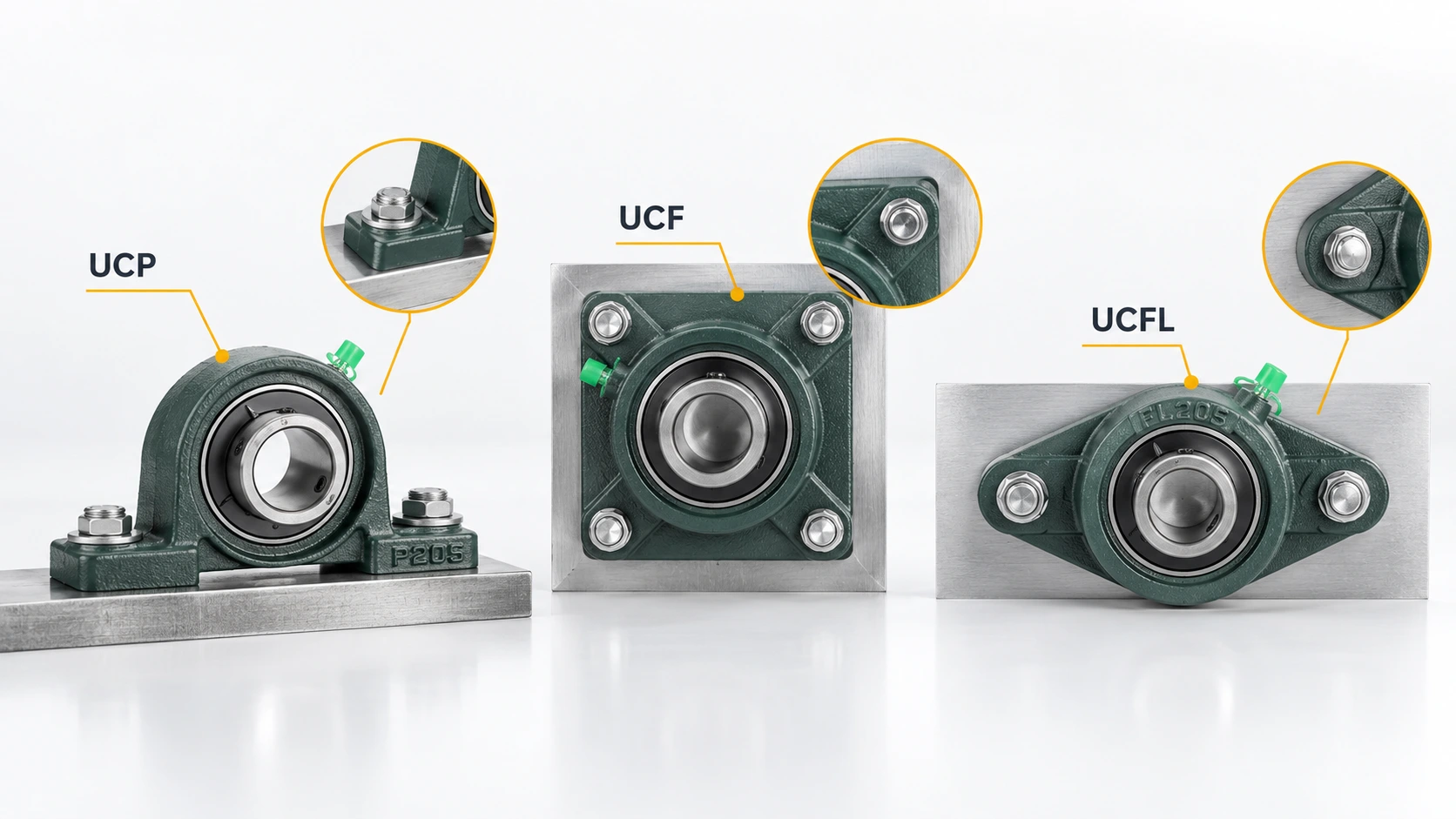
The fastest way to choose among UCP, UCF, and UCFL mounted bearing units is to start with the structure around the shaft. ইউসিপি is generally the base-mounted option, ইউসিএফ is the square-flange option for a face or wall, and ইউসিএফএল is a two-hole flange style for compact mounting. Load direction then confirms whether the selected housing and insert bearing are suitable. This guide explains the decision in that order and points to the relevant pillow block bearing range from LQYS Bearings for model-level verification.
What the three designations mean
All three are mounted bearing units: an insert ball bearing is installed in a housing so the shaft can be supported with a ready-to-mount assembly. The bearing code identifies the insert size, while the letters describe the housing form. The housing changes the footprint, bolt pattern, and practical load path; it does not remove the need to check shaft size, speed, lubrication, sealing, and rated load in the final specification.
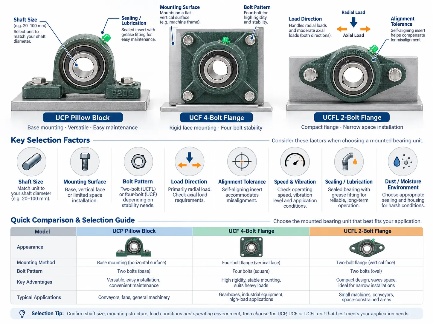
| সিরিজ | Housing and mounting | Space implication | Typical decision |
|---|---|---|---|
| ইউসিপি | Vertical housing with a base | Needs a flat base and clearance around the pedestal | Use when the shaft runs above a machine frame and a conventional pedestal is available |
| ইউসিএফ | Square flange with four mounting points | Uses a face or wall plate; the square footprint needs corner clearance | Use when a rigid face mount and stable bolt pattern are important |
| ইউসিএফএল | Flange housing with two mounting holes | Compact two-hole layout helps when plate area is limited | Use when mounting space is tight or the support plate is narrow |
Choose by mounting space
Measure the support surface before comparing load ratings. Record the available length and width, bolt-hole spacing, shaft center height, surrounding guard clearance, and the direction from which the shaft enters the housing. A series that fits the shaft but conflicts with the plate or guard will create rework during installation.
UCP when a base mount is available
Choose UCP when the machine frame provides a horizontal mounting surface and the shaft centerline can sit above it. The LQYS UCP page describes a compact vertical housing, two set screws for fixing the inner ring, and multiple size families such as P200 and P300. Those features support straightforward installation and adjustment, but the actual center height and bolt dimensions must be checked against the drawing for the selected bore. Leave tool access for tightening the set screws and enough room to remove the unit during maintenance.
See the UCP series product page for the available model families.
UCF when face mounting and rigidity matter
UCF is the practical choice when the bearing must bolt to a vertical plate, side wall, or end face. Its square flange spreads the reaction through four mounting points, so the support plate and bolt pattern become part of the load path. LQYS describes the outer ring as spherical so the insert can self-align within the housing when the shaft has a limited angular error. That feature helps with minor alignment variation; it does not compensate for a bent shaft, a weak plate, or excessive structural deflection.
Review the UCF series product page when a square flange matches the machine frame.
UCFL when plate area is limited
UCFL uses a flange housing with two mounting holes. The reduced bolt count can simplify a narrow support plate or a retrofit where neighboring components limit corner clearance. The LQYS product description also notes that UCFL units can be installed vertically, at an incline, or at another practical angle, provided the support is designed for the resulting reaction. Confirm the hole spacing, housing height, shaft access, and guard envelope before treating the compact footprint as a direct substitute for UCP or UCF.
Compare models on the UCFL series product page.
Match the housing to load direction
Start with radial load
Most mounted insert units are selected first for a radial load acting perpendicular to the shaft. Calculate the load at each bearing from belt pull, chain tension, gear force, rotor weight, and the distance between supports. Include shock or impact factors when the machine starts, stops, reverses, or handles uneven material. The housing shape changes how the reaction reaches the frame, so a correct bearing insert can still fail if the base or flange twists.
Check combined radial and axial load
Many conveyor, fan, agricultural, and general machine arrangements impose a small axial component along with the main radial force. UCF and UCFL product information describes service under radial, light axial, and combined loads, while emphasizing that the insert is not intended to carry a large axial load by itself. Use the manufacturer rating and the load combination method for the exact UC insert rather than comparing housing letters as if they were load classes.
Treat axial load as a limit condition
If thrust is a primary duty, a mounted insert unit may be the wrong architecture. The UCF page states that, with its set-screw arrangement, allowable axial load should not exceed 20% of rated dynamic load. Treat that value as a product-specific condition to verify in the current technical data, not as a universal rule for every UC insert or housing. Consider a dedicated locating bearing or thrust arrangement when the axial reaction is continuous, high, or subject to reversal.
A practical selection workflow
-
Map the shaft and support: bore, shaft orientation, center height, plate thickness, available footprint, and service access.
-
Select the housing form: UCP for a base, UCF for a square face flange, or UCFL for a compact two-hole flange.
-
Resolve the load: radial, combined, or mainly axial; include shock, belt or chain tension, and misalignment.
-
Verify the insert: dynamic and static ratings, speed, locking method, sealing, lubrication, temperature, and permissible misalignment.
-
Check the installation drawing: bolt spacing, shaft extension, set-screw access, guard clearance, and replacement envelope.
Installation and verification checks
A mounted unit should sit on a clean, flat support. Tighten the housing fasteners evenly, align the shaft before locking the insert, and rotate the shaft by hand to detect binding. Recheck set-screw torque and axial float after the first run if the application allows. In contaminated or humid areas, confirm that the seal arrangement and relubrication interval match the environment. The LQYS pages describe pre-lubricated units, but maintenance intervals still depend on speed, temperature, contamination, and duty cycle.
When to ask for a fit check
Send the supplier the model or bore, shaft diameter, mounting drawing, load components, speed, temperature, contamination level, quantity, and application. LQYS Bearings presents UCP, UCF, and UCFL as part of its pillow block range and can use those details to confirm the nearest model and the information still required for approval. For a formal RFQ, use the technical contact channel.
উপসংহার
Choose the housing from the machine first, then qualify the bearing for the load. UCP fits a supported base, UCF fits a square face flange, and UCFL fits a compact two-hole plate. Radial and modest combined loads are common, while a dominant axial load requires a separate engineering check. A short drawing review before ordering prevents most interchange and clearance problems.
প্রশ্নাবলী
Is UCP stronger than UCF or UCFL?
The series letter describes housing geometry, not a universal strength ranking. Compare the insert rating, housing dimensions, support stiffness, fasteners, and actual load.
Can UCFL replace UCF?
Only when the bolt pattern, shaft centerline, surrounding clearance, support stiffness, and load path all match. Verify the selected model drawing before substitution.
Which series is best for a vertical shaft?
UCF or UCFL can suit a vertical or angled arrangement when the support and load direction are acceptable. UCP is chosen when its base orientation and center height fit the frame.
Do these units handle axial load?
They can accommodate limited axial or combined loading depending on the insert and mounting method. A mainly axial duty should be reviewed as a dedicated thrust problem.